ASIC/FPGA Design and Verification Out Source Services
VHDL IP Stack
In this page I'll explain the simple test, which I did to quickly test the RX. This is as a first shot to understand the code.
- The data process first starts at the MAS component, which handles the physical layer.
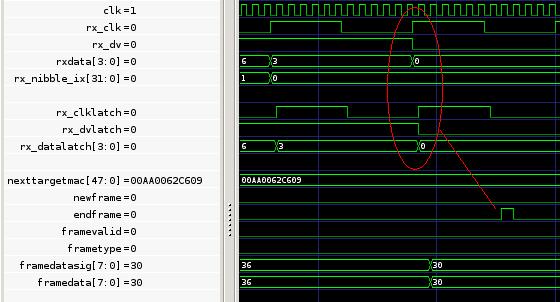
- The component outputs an indication, if the frame is valid, for ARP or internet type. This is when new_frame signal is asserted. '0' means ARP and '1' means internet on the output frame type. This indication is used in the next components, that follow in the data path.This is shown in the next wave diagram:
 Press here to increase the pictureFirst the red circle in the wave diagram is where the PHY outputs the last preamble byte. Next is the blue circle. This is the destination MAC address as defined in the code global constant VHDL file.Last on the right bottom is a green circle, that is the component output indication. Press here to increase the pictureFirst the red circle in the wave diagram is where the PHY outputs the last preamble byte. Next is the blue circle. This is the destination MAC address as defined in the code global constant VHDL file.Last on the right bottom is a green circle, that is the component output indication.
- The following wave diagram shows the end of the frame.
 Press here to increase the pictureI needed to change the bit order of the byte being fed to the ETHERNET receive component. While the ETHERNET component identified all fields of my valid ICMP frame, the CRC component failed in CRC calculation:
frameDataSig_r <= --pini
frameDataSig(0) & frameDataSig(1) &
frameDataSig(2) & frameDataSig(3) &
frameDataSig(4) & frameDataSig(5) &
frameDataSig(6) & frameDataSig(7);
-- instantiate the CRC generator component
crcGenEthRec : crcGenerator port map (
clk => clk,
rstn => rstn,
newFrame => CRCNewFrame,
newByte => newByte,
inByte => frameDataSig_r, --pini
crcValid => open,
crcValue => CRC
); Press here to increase the pictureI needed to change the bit order of the byte being fed to the ETHERNET receive component. While the ETHERNET component identified all fields of my valid ICMP frame, the CRC component failed in CRC calculation:
frameDataSig_r <= --pini
frameDataSig(0) & frameDataSig(1) &
frameDataSig(2) & frameDataSig(3) &
frameDataSig(4) & frameDataSig(5) &
frameDataSig(6) & frameDataSig(7);
-- instantiate the CRC generator component
crcGenEthRec : crcGenerator port map (
clk => clk,
rstn => rstn,
newFrame => CRCNewFrame,
newByte => newByte,
inByte => frameDataSig_r, --pini
crcValid => open,
crcValue => CRC
);
- Since this is an internet frame the data is next processed at the netwroklayer internet component.
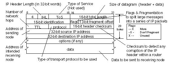
- The module first checks for a correct ip version:
-- check ip version
if frameDataLatch (7 downto 4) /= "0100" then ...
This is shown in the next wave diagram: 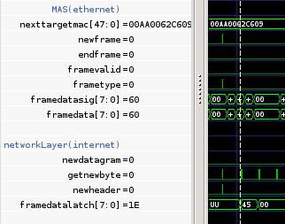 Press here to increase the picture Press here to increase the picture
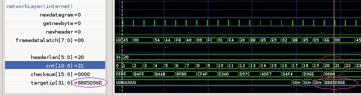
- Next thing to check is checksum (should be 0 if calculated okay) and target IP should match the DEVICE IP, defined in global package. This is shown in the next wave diagram:
 Press here to increase the picture
Note: I changed the code global DEVICE IP, because I was too lazy to calculate the checksum in IP frame, which I downloaded from the WEB. Press here to increase the picture
Note: I changed the code global DEVICE IP, because I was too lazy to calculate the checksum in IP frame, which I downloaded from the WEB.
- The network layer component did not assert the new data gram indication due to a VHDL issue. While some simulators may be forgiving, this is not the case with GHDL:--if cnt = headerLen then if cnt = ("00000" & headerLen) then
- The network layer componet also extarcts the protocol field.
 In this case the protocol indication is 01 (1 = ICMP; 2= IGMP; 6 = TCP; 17= UDP). This is output to next layers, when the signal newDatagram is asserted. In this case the protocol indication is 01 (1 = ICMP; 2= IGMP; 6 = TCP; 17= UDP). This is output to next layers, when the signal newDatagram is asserted.
- The network layer component is responsible to extract and store into the SRAM the ICMP code (0x08). When the ICMP component starts its frame analysis, it checks for that value:
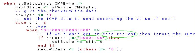 Press here to increase the picture
To go back to main VHDL IP project: VHDL IP stack main page Press here to increase the picture
To go back to main VHDL IP project: VHDL IP stack main page
Contact me now at: |