ASIC/FPGA Design and Verification Out Source Services
FFT system C project - 8 point FFT using DIT algorithm.
- I have considered a few ways to implement the FFT data path design: a) using a constant width vector for all internal data in the assorted FFT stages, b) increasing width vector for internal data.
- A constant width vector data facilitates the implementation. This comes on the expense of input dynamic signal amplitude (The difference between the highest allowable signal value to the lowest one). If the input is too high (or to low), data errors appear. Let us now consider smaller designs, than the eight point FFT, like a simple two input 8 bits adder or multiplier. As an example consider first a simple adder. For a constant width 8 bit signed number the maximum positive number is 127. So the maximum input to an adder is 63. So when the possible two largest numbers are added, the result do not cross 127. The FFT introduces some gain. In the assorted stages of the FFT, there are both adders and multipliers, each contributes to the dynamic input range reduction, if a constant width option is selected.
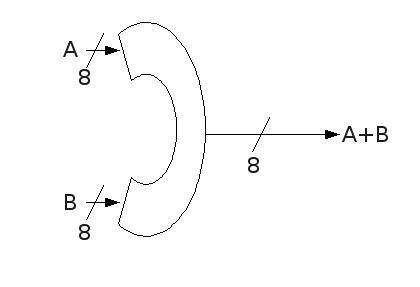
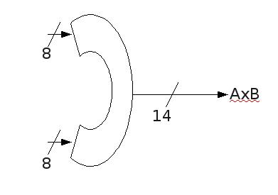
- A variable bit data representation, overcomes the dynamic range reduction, but it complicates the design. On each stage the data path has to be increased, depanding on calculation done in the stage.Again I present the simple adder / multiplier example, to facilitate the explaination. So if the adder has inputs of 8 bits the output has to be of 9 bits width. Let us consider a multiplier for this example. For a multiplier with the same two inputs having width of 8, a 14 bits output is required: 127*127=16129=0x3f01.
- The first option, constant width vector, was selected, for this implementation, in order to keep the implementaion simple.
- In order to simplify the design, data is represented as whole integers. I do not break a number into two parts: one portion is for the whole number and another is for the fractional.
- This has some implications on accuracy and again on the input dynamic range. This shown in the VHDL equation. In the first stage no fractional number are required for the twiddle factor, so I just multiply every factor by 8.

- The accuracy issue is because some of the twiddle factors are fractional numbers. To overcome it, I multiply by a factor all data. So we get a twiddle factor greater than one.
- For the last stage with non fractional twiddle factors, we multiply the input, using the same value, reducing farther the dynamic input.
- In this design I have selected a value of 8. This does not really requires a multiplier, as the operation is simply shift operation.
- Fortunately the fractional twiddle factor is of the form of: real part or imaginary part has the value of +1 or -1. The rest are as in former stages. So actually the number 0.070710678 is required. After multiplying by 8 and rounding up we get 6. This is also not implemented by a regular multiplier. We multiply by 6 and 4 and add the results, again taking advantage of multiplying by a power of 2.
- Return to the FFT main page. FFT main page .
-
A complex multiplier (two-dimensional Cartesian coordinate is used at
both of its inputs and outputs)
using only three
scalar multipliers, to save chip area, is also available
on this site:
from:
Please let me know what you think on this FFT work.
Contact me now at: |